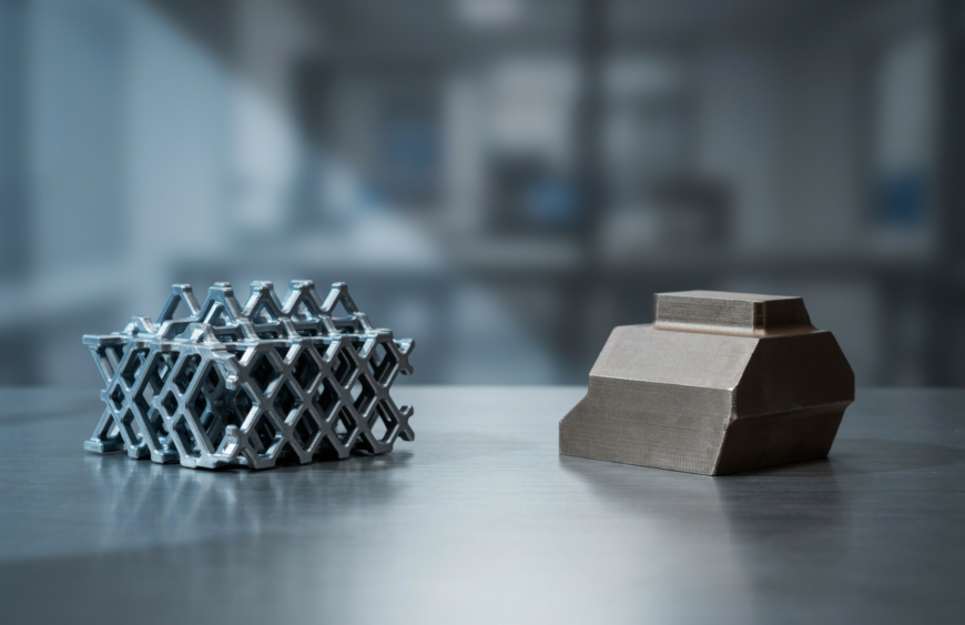
Quick answer: MJF (Multi Jet Fusion) is a powder-bed 3D printing process developed by HP and introduced in 2016. It jets a fusing agent and a detailing agent onto a layer of nylon powder, then passes an infrared energy source over the bed to fuse the treated areas. SLS (Selective Laser Sintering) also builds parts from powder, but a laser traces and sinters each cross-section. Both make strong nylon parts without support structures. MJF is known for more uniform strength and faster cooling and powder recovery. SLS offers a wider material range and larger build volumes.
If you’re choosing a process for prototypes or end-use parts, the sections below show where each technology fits.
1. What Is MJF 3D Printing?
Multi Jet Fusion is a powder-bed fusion process that builds plastic parts layer by layer from fine thermoplastic powder. HP launched it in 2016, aiming at functional prototypes and low-to-mid volume production. HP describes it as a combination of powder bed fusion and binder jetting.
MJF needs no support structures. The surrounding unfused powder holds every part in place during the build. This allows internal channels, lattices, hinges, and interlocking assemblies without support removal marks.
Parts have a matte, slightly grainy surface and are typically light grey because the fusing agent is dark. They are usually dyed black when a uniform finish is needed.
2. How Does the MJF Process Work?
- Powder recoating: A thin layer of nylon powder is spread over the build platform and heated to just below its sintering temperature.
- Agent application: An inkjet-style carriage jets a fusing agent where the part will be solid. It also jets a detailing agent around the edges to sharpen boundaries and limit heat spread.
- Energy application: An infrared source passes over the bed. Areas with fusing agent absorb heat and fuse, while untreated powder stays loose.
- Repeat: The platform lowers and the cycle continues until the build is complete.
- Cooling and cleaning: The build cools, then parts are removed from the powder and cleaned, usually by bead or air blasting.
Because the agents and heat are applied across the whole layer rather than traced point by point, the process suits batches of many parts.
3. What Is SLS 3D Printing?
Selective Laser Sintering is the older of the two technologies, developed in the 1980s. A recoater spreads a layer of polymer powder, then a laser, typically a CO₂ laser, scans each cross-section and sinters the particles together. The bed lowers, fresh powder is spread, and the cycle repeats.
Like MJF, SLS needs no dedicated supports. It is a mature process with a broad range of materials and machine platforms.
4. MJF vs SLS: Key Differences
| Factor | MJF | SLS |
| Fusing method | Fusing and detailing agents, then infrared energy across the layer | Laser scans and sinters each cross-section |
| Typical part colour | Light grey; can be dyed black | White or off-white; grey powder also available; can be dyed many colours |
| Cooling and powder recovery | Faster, with dedicated post-processing stations | Typically longer cooling |
| Powder reuse | Often cited at 80–85% | Often cited at 30–50% |
| Mechanical properties | Highly uniform in all directions | Strong; some directional variation, especially along Z |
| Feature resolution | Finer (about 0.5 mm) | About 0.76 mm for nylons |
| Max build volume | Up to about 380 × 284 × 380 mm | Larger, up to about 750 × 550 × 550 mm on some machines |
| Materials | PA 12, PA 11, glass-filled PA 12, PP, TPU | Broader: also flame-retardant, metal-filled, and high-temperature grades |
Speed and turnaround
Layer time is similar for both, because recoating drives most of the build time. The real difference comes after printing. MJF builds cool faster and powder recovery is quicker, so operators can run builds more continuously. That usually means shorter lead times.
Strength and mechanical consistency
Tensile strength for PA 12 is close on both processes, roughly 48–50 MPa. The difference is directional behaviour. Published PA 12 data shows elongation at break along the Z axis of about 15% for MJF versus about 4% for SLS. MJF parts are therefore often more predictable under multi-directional loads. Material choice and part geometry still matter more than the process label.
Surface finish
Both processes produce a grainy, matte surface straight off the machine, and neither is clearly smoother. Measured as-printed roughness (Ra) for PA 12 is in the same range for both. Finishing makes the real difference: media tumbling, vapour smoothing, dyeing, and painting or plating can improve either process.
Accuracy
Both achieve about ±0.3% tolerances. MJF has a slightly tighter lower limit of about ±0.2 mm versus ±0.3 mm for SLS, and its 1200 DPI printheads help it resolve small features.
Material choices
SLS has the broader material pool, including flame-retardant, high-temperature, and metal-filled options. MJF covers the common engineering needs: PA 12 and PA 11 for tough parts, glass-filled PA 12 for stiffness, polypropylene, and TPU for flexible parts.
5. Strengths of MJF
- Consistent properties: More uniform strength across X, Y, and Z.
- Design freedom: No supports, so complex internal geometry is practical.
- Fine detail: Small features, thin walls (about 0.6 mm minimum), and small text print cleanly.
- Faster turnaround: Quicker cooling and powder recovery keep production moving.
- Functional nylon parts: Tough, wear-resistant, and suited to snap-fits, housings, and brackets.
6. Where SLS Still Makes Sense
- Specialised materials: Flame-retardant, glass-filled, aluminium-filled, and high-temperature composite nylons are available on SLS platforms. See the materials we offer.
- Flexible parts: TPU elastomer grades suit gaskets, seals, and flexible joints.
- Larger parts: SLS machines generally offer bigger build volumes.
- Light base colour: A white or off-white base suits dyeing and painted finishes.
- Prototypes before tooling: SLS parts are a practical way to validate a design before committing to rapid tooling for injection moulding.
- Validated designs: If a design was already proven on SLS, staying on it keeps results consistent.
Neither technology is better in every case. The right choice depends on part size, material, finish, and quantity.
7. Common Applications
Both processes are widely used for:
- Functional prototypes for real-world testing
- Enclosures and housings for electronics
- Brackets, clips, and jigs and fixtures for assembly lines
- Ducting and parts with internal channels
- Gaskets, seals, and flexible joints in TPU
- Small-run end-use parts across aerospace, automotive, medical technology, consumer products, and robotics
8. Design Tips for Powder-Bed Printing
- Add escape holes to hollow parts so loose powder can be removed.
- Keep walls consistent. The minimum is about 0.6–0.7 mm, and about 1 mm is recommended for structural areas. Our guide to wall thickness and tolerances covers this in detail.
- Avoid large flat areas. Both processes can warp.
- Don’t design to the full build size. Oversized parts raise warping and build-failure risk.
- Plan finishing early. Dyeing, painting, or plating can affect final dimensions and appearance. Understanding DFM early saves iterations.
9. How to Choose Between MJF and SLS
- Material: Confirm your grade exists on the process you pick.
- Part size: Large parts may need SLS’s bigger build volume.
- Load direction: Multi-directional loads favour MJF’s uniformity.
- Colour and finish: Grey or black suits MJF. Other colours suit SLS.
- Quantity and timeline: Repeat batches often favour MJF’s faster turnaround.
If neither powder process fits, other options include SLA for fine detail and smooth surfaces, FDM for low-cost functional models, and DMLS for metal parts.
10. SLS 3D Printing at Tesseract3D
Tesseract3D offers SLS 3D printing in Mumbai for functional prototypes and low-volume production, with support-free printing and delivery across India. Parts can be produced in a range of nylon-based DuraForm materials:
- DuraForm ProX PA: strong, tough polyamide for production parts
- DuraForm GF / ProX GF: glass-filled for stiffness
- DuraForm FR1200: flame retardant
- DuraForm ProX AF+: aluminium-filled nylon 12 with a metallic look
- DuraForm ProX HST Composite: fibre-reinforced for high temperature resistance
- DuraForm TPU Elastomer: rubber-like flexibility
Finishing options include painting, hydro-dipping, hydro-chroming, electroplating, and insert installation through post-processing. If you’re still developing the part, the product design team can help prepare it for printing.
Share your CAD file through the contact page for a quote and design review. The team can advise whether SLS suits your requirements.
Frequently Asked Questions
Are MJF and SLS the same?
No. Both are powder-bed fusion processes that make similar nylon parts without supports. They differ in how they fuse the powder. SLS uses a laser, while MJF uses fusing and detailing agents plus infrared energy.
Is MJF or SLS stronger?
Tensile strength in PA 12 is similar for both. MJF is known for more uniform strength in all directions, especially along the Z-axis. SLS parts are also durable. Material and geometry matter more than the process, so test with your own part.
Do MJF and SLS parts need support structures?
No. Unfused powder surrounds and supports the part during the build. This allows complex shapes and interlocking assemblies without separate supports.
Why are MJF parts grey?
The fusing agent contains a dark component that absorbs infrared energy. This colours the fused material light grey. Parts can be dyed black afterward.
Which is better for production runs, MJF or SLS?
MJF is often preferred for repeat batches because cooling and powder recovery are faster, which shortens turnaround. SLS can be the better fit when you need a specific material, a lighter base colour, or a larger part. A manufacturer can advise based on your design and quantity.