The right wall thickness and tolerances depend on the printing process. As a starting point:
- SLS: walls of about 0.7 to 1 mm and moving-part clearances of 0.4 to 0.5 mm.
- SLA: walls of about 0.5 mm when supported and 1 mm when free-standing, with the finest detail at layers as thin as 25 microns.
- FDM: walls of at least 0.8 mm (twice a 0.4 mm nozzle), with 1.2 mm or more for strength.
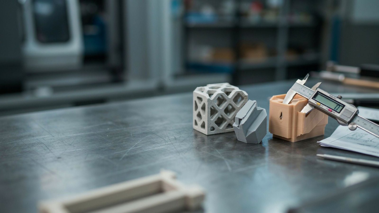
A 3D-printed part can look perfect on screen and still fail in your hand. Walls that are too thin warp or snap. Fits that are too tight fuse together or refuse to assemble. Most of these failures come from one mistake: designing every part the same way, regardless of how it will be printed. SLS, SLA, and FDM each build parts differently, so each needs its own design rules.
Why These Two Design Choices Decide Success
Wall thickness controls strength, stiffness, and printability. Too thin, and the wall may not form properly or may distort as it cools or cures. Too thick, and you add weight, cost, and print time, and in some processes you increase the risk of warping.
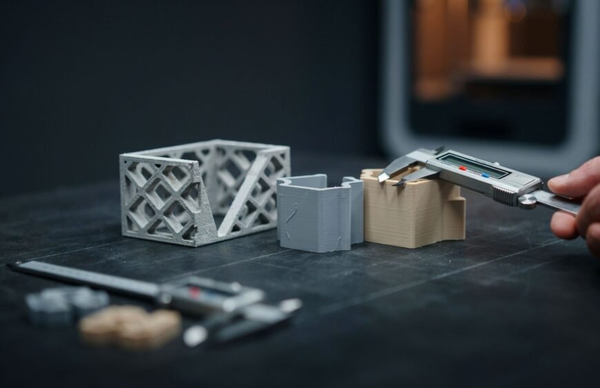
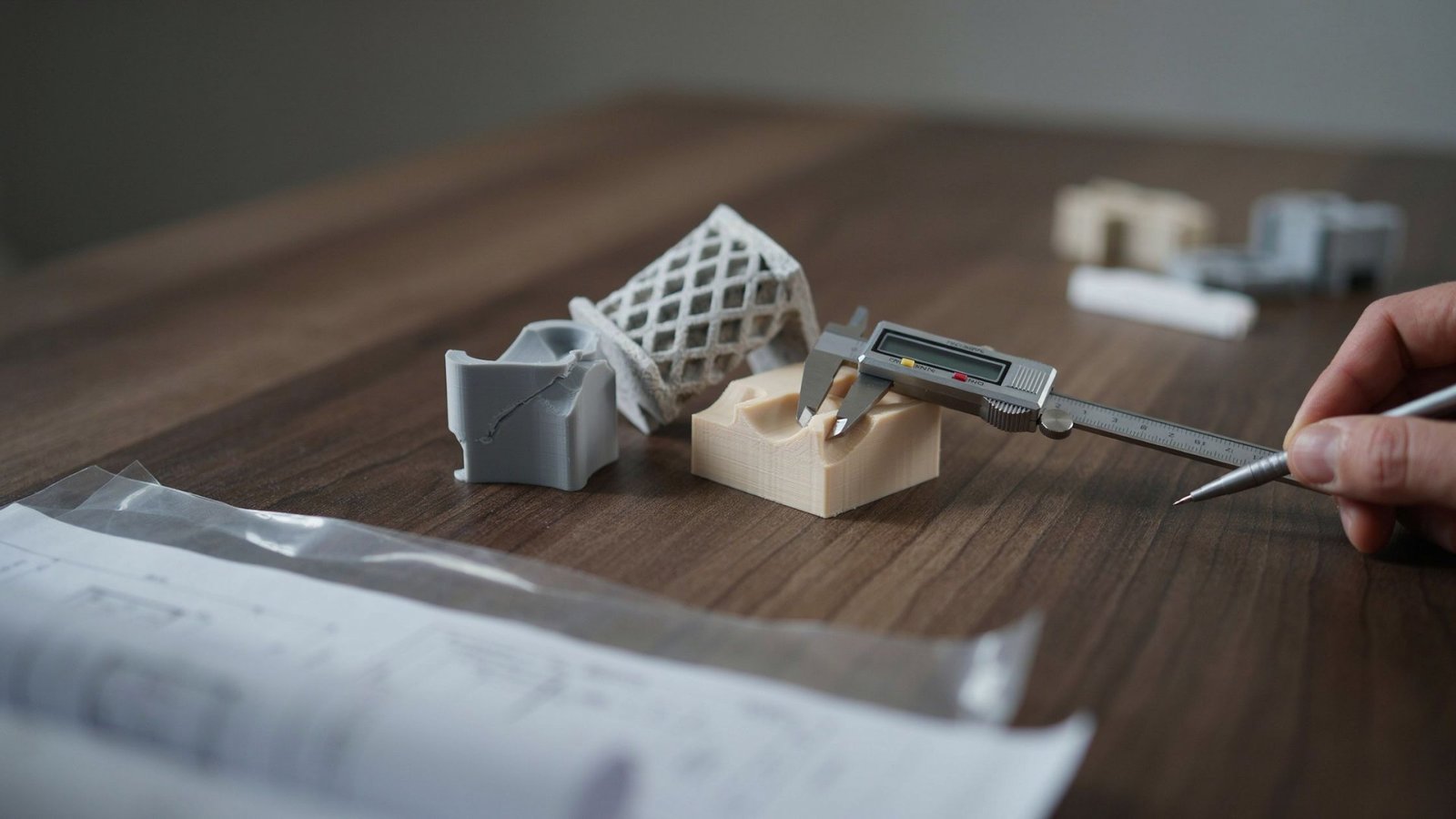
Tolerance is the acceptable variation between the CAD dimension and the printed dimension. It decides whether a snap fit clicks, a pin slides into a hole, or two halves of an enclosure close cleanly. Getting it right means planning for how much the process will deviate, rather than hoping the printer matches the CAD model exactly.
What Controls Accuracy in Any Printed Part
Before looking at each process, it helps to understand the four factors that affect dimensional accuracy across all of them:
- Layer thickness: thinner layers give finer vertical detail and smoother curves.
- Build orientation: features printed flat in the XY plane are usually more accurate than those built up through many layers.
- Thermal behaviour: materials that are heated and then cool, or resins that cure, can shrink and distort slightly.
- Supports and post-processing: support removal, sanding, and curing can all change final dimensions.
Good design accounts for all four, not just the nominal CAD size.
Designing for SLS
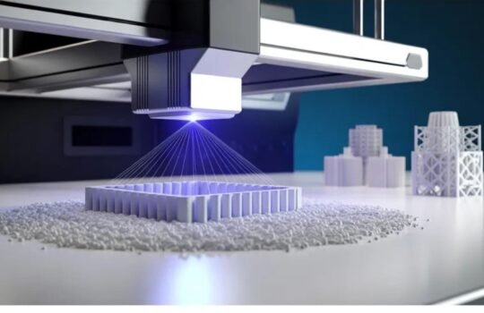
SLS 3D printing uses a laser to fuse polymer powder, most commonly nylon PA12 or PA11, layer by layer. Layer thickness is typically around 0.1 mm. Because the unsintered powder supports the part during printing, SLS needs no support structures, which gives designers a lot of freedom.
Key rules for SLS:
- Keep walls at roughly 0.7 to 1 mm minimum for structural integrity. Stiffer filled grades, such as carbon-filled nylon, need up to 2 mm.
- Use ribs instead of thick panels. Large flat panels warp as they cool. Adding ribs is usually better than thickening the whole wall, because thick sections shrink more than thin ones.
- Leave 0.4 to 0.5 mm clearance between moving parts so they do not fuse during sintering, and around 0.3 mm for static interlocking parts.
- Add escape holes to hollow sections, at least 3.5 to 4 mm in diameter and ideally two per cavity, so trapped powder can be removed.
- Allow for cooling. The build chamber must cool slowly before parts are removed, often for several hours, and rushed or uneven cooling is a common source of distortion.
Tolerances: SLS typically holds about ±0.3% of the dimension, with a lower limit of ±0.3 mm. The Z-axis is usually the least accurate.
SLS parts are nearly isotropic, with strength that varies far less by direction than FDM parts. That makes SLS a strong choice for functional prototypes, snap fits, and end-use parts. PA11 is more flexible and impact-resistant, making it well suited to living hinges and snap fits. Glass-filled nylon adds stiffness for structural parts.
Designing for SLA
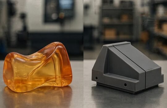
SLA 3D printing uses a laser to cure liquid photopolymer resin layer by layer, producing smooth surfaces and very fine detail. With layer thicknesses as fine as 25 microns, it is the best choice among the three when small features, crisp edges, and tight visual accuracy matter. Typical uses include dental models, jewellery and detailed prototypes. This guide to high-resolution 3D printing techniques covers when that level of detail is worth it.
Key rules for SLA:
- Plan around 0.5 mm for supported walls and 1 mm for free-standing walls. Resin parts can distort slightly during curing and post-curing, so thin, unsupported walls are the most vulnerable. They are also easily damaged during washing and support removal.
- Plan support placement. SLA needs supports, and the surfaces they touch will need finishing, so keep critical faces and mating surfaces away from support contact points.
- Add drain holes to hollow parts so uncured resin can escape and does not cause suction or pooling.
- Choose resin to match function. Engineering resins range from rigid, ABS-like grades to clear and high-temperature options, and each behaves differently under load.
Tolerances: SLA is the most accurate of the three, typically around ±0.1 to ±0.2 mm on well-calibrated machines. Its fine resolution allows tighter clearances than FDM, often around 0.2 mm, but mating parts should still be tested before committing to a full batch. If you are weighing resin processes for fine detail, this comparison of PolyJet and SLA for high-detail prototypes explains the trade-offs.
Designing for FDM
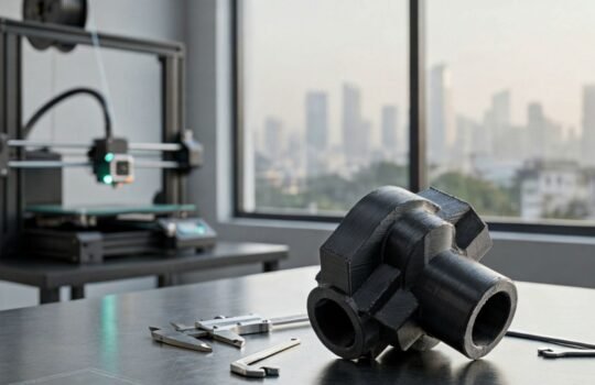
FDM 3D printing heats a thermoplastic filament and deposits it along a set path, layer by layer. It is affordable, fast, and works with a wide range of materials, from PLA and PETG to engineering polymers such as PEEK, polycarbonate and carbon-fibre-reinforced grades.
Key rules for FDM:
- Design walls as multiples of the extrusion width. Walls in FDM are built from individual extruded lines, so a 0.4 mm nozzle prints best at 0.8 mm, 1.2 mm or 1.6 mm. Use 0.8 mm as the minimum and 1.2 mm or more for parts that carry load.
- Orient critical features carefully. Holes printed vertically, with their axis pointing up, stay rounder than holes printed horizontally.
- Expect more variation in the Z direction. Layer lines make vertical dimensions and curved surfaces less precise than those in the XY plane.
- Plan secondary finishing for precise fits. Drilling or reaming holes after printing is a reliable way to hit tight fits.
- Consider strength direction. FDM parts are usually weakest between layers, so orient parts so loads run along the layers where possible.
Tolerances: desktop FDM typically holds around ±0.5% with a lower limit of ±0.5 mm, while industrial machines reach about ±0.3% with a lower limit of ±0.3 mm. Leave 0.3 to 0.5 mm clearance between mating parts.
Quick Comparison
| Factor | SLS | SLA | FDM |
| Support structures | Not needed | Needed | Needed for overhangs |
| Layer thickness | About 0.1 mm | As fine as 25 microns | Typically 0.1 to 0.3 mm |
| Minimum wall guidance | 0.7 to 1 mm (up to 2 mm for filled grades) | About 0.5 mm supported, 1 mm free-standing | 0.8 mm minimum, 1.2 mm+ for strength |
| Typical tolerance | ±0.3% (lower limit ±0.3 mm) | About ±0.1 to ±0.2 mm | ±0.3% to ±0.5% (lower limit ±0.3 to ±0.5 mm) |
| Moving-part clearance | 0.4 to 0.5 mm | About 0.2 mm | 0.3 to 0.5 mm |
| Best for | Functional, near-isotropic parts | Fine detail, smooth finish | Low-cost prototypes, large parts |
These values are starting points. Exact limits vary by machine, material, and part geometry, so confirm critical features with a test print.
Practical Rules for Holes, Pins and Fits
Whatever the process, a few habits prevent most fit problems:
- Always add clearance between mating parts rather than modelling them at identical sizes.
- Print a small test coupon of your critical fit before printing the full part.
- Keep wall thickness consistent across a part to reduce uneven shrinkage, and blend any thickness changes gradually.
- Add material where you will finish. If a surface will be sanded, blasted, or painted, leave a little extra thickness on critical dimensions to allow for material removal.
- Put your tightest tolerances only where they are needed, since specifying them everywhere raises cost without adding value.
If you are recreating an existing part, 3D scanning and reverse engineering capture the real dimensions first, so clearances can be designed around measured geometry rather than estimates. For load-bearing fits that need machine-level precision, a printed part can be finished with CNC machining on the critical faces.
Getting Expert Help With Your Next Build
Tesseract brings over a decade of experience in 3D printing, design, and CNC machining. It operates from its Mumbai head office in Prabhadevi and a manufacturing facility in Boisar, with 5,000+ sq. ft. of space and 100+ machines covering FDM, SLA, SLS, DMLS, DLP, and PolyJet. That range means Tesseract can recommend the right process for your part’s function rather than forcing every design into one technology.
Its FDM facility is one of India’s most extensive, with machines of various build volumes. Its material range spans engineering polymers, Accura SLA resins and DuraForm SLS powders. Tesseract also offers 3D CAD modelling, reverse engineering and 2D to 3D conversion, so wall thickness and tolerances can be optimised before printing begins. Most projects are completed within 2 to 7 days, with expedited options for urgent deadlines.
Upload your design to Tesseract for a quote and expert design feedback.
Frequently Asked Questions
What is the minimum wall thickness for SLS parts?
SLS walls should be at least 0.7 to 1 mm thick for structural integrity, and up to 2 mm for stiffer filled nylon grades.
What is the minimum wall thickness for FDM printing?
FDM walls should be at least 0.8 mm with a standard 0.4 mm nozzle, and 1.2 mm or more for parts that carry load.
What is the minimum wall thickness for SLA printing?
Supported SLA walls can be around 0.5 mm, while free-standing walls should be about 1 mm to survive curing and handling.
Which process is most accurate: SLS, SLA, or FDM?
SLA is the most accurate, typically around ±0.1 to ±0.2 mm, followed by SLS at about ±0.3 mm, with FDM usually the least accurate.
How much clearance do moving SLS parts need?
Leave 0.4 to 0.5 mm between moving parts so they do not fuse during sintering, and about 0.3 mm for static interlocking parts.