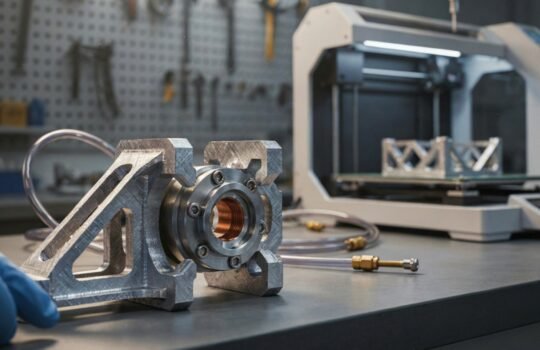
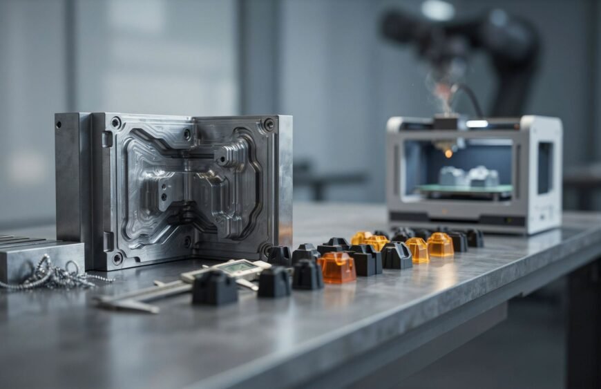
Rapid tooling is the fast, lower-cost production of moulds or mould inserts, used to make real parts for testing and short runs before a business commits to full production tooling.
Every injection moulded product starts with a mould, and that mould is often the slowest and most expensive part of the project. Hardened steel tools can take weeks to machine and take up a large share of the launch budget. If the design changes after the steel is cut, the cost and the delay repeat. Rapid tooling solves this by giving product teams a quicker, cheaper mould to work with first. Teams can then validate designs with real moulded parts before locking anything in.
What the Term Actually Means
In the plastics industry, rapid tooling refers to moulds built in days or a few weeks, instead of the 6 to 12 weeks typical for a hardened steel production tool. It is also called prototype tooling. When it fills the gap between prototyping and mass production, it is often called bridge tooling.
The key difference from conventional tooling is purpose. A production tool is built to run hundreds of thousands of cycles with minimal wear. A rapid tool is built to answer questions quickly: Does the part fit? Does it function? Will customers like it? Because the process starts from a CAD file, teams can move from digital model to physical mould in a fraction of the usual time.
Why Conventional Mould Making Slows Projects Down
Injection moulding is the preferred method for producing plastic components in large quantities, thanks to its tight tolerances and repeatability. If you are new to the process, this step-by-step guide to how injection moulding works covers the basics. The trade-off is the upfront investment. Creating a mould tool is expensive and time-consuming, which makes injection moulding less practical for very low-volume production.
This creates three common bottlenecks:
- Long lead times before the first real part is in hand
- High financial risk if the design has an undiscovered flaw
- Costly revisions, since modifying a hardened steel cavity is slow and expensive
Rapid tooling reduces all three by moving testing and learning to the front of the project, when changes are still cheap.
What Makes a Quick-Turn Mould Faster to Build
The speed comes from removing the slowest steps of conventional mould making:
- Softer tool materials: Aluminium machines several times faster than hardened steel and causes less cutter wear.
- Standard mould bases: Only the core and cavity inserts are custom-made, which saves days of machining.
- Fewer secondary processes: Time-consuming steps such as electrical discharge machining (EDM) are reduced or avoided where possible.
- Simplified actions: Complex slides and side actions are often replaced with hand-loaded inserts, which is acceptable at low volumes.
- Single-cavity layouts: One cavity is enough for validation and short runs.
Direct and Indirect Approaches
Most rapid tooling methods fall into one of two groups.
Direct tooling builds the mould or mould insert straight from the CAD file, by 3D printing or machining. It is the quickest route from design to moulded part.
Indirect tooling first produces a master pattern, then uses that pattern to form the mould. Silicone moulds for vacuum casting are the most common example. This route suits highly detailed parts and lets teams make several moulds from one pattern.
The Main Types of Fast Tooling
There is no single method. The right approach depends on part volume, material, and required finish.
- 3D printed mould inserts
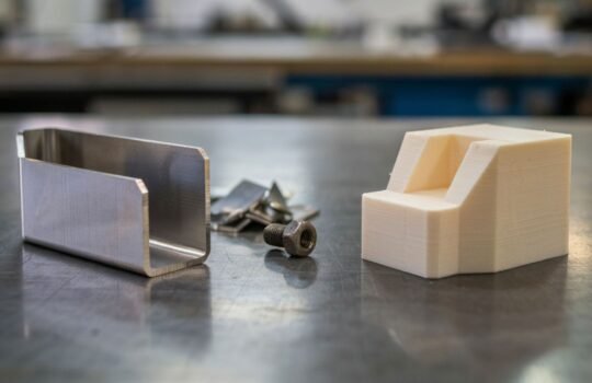
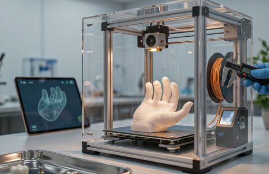
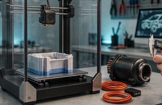
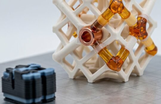
High-temperature SLA and DLP resins can produce mould inserts directly from CAD, with no machining. They suit short runs, typically tens to a few hundred parts, in lower-temperature thermoplastics. Printed inserts are a fast way to get early moulded samples. High-resolution processes such as MultiJet Printing (MJP) are better suited to producing detailed master patterns, including castable wax patterns for metal casting. - Machined soft metal tools
Aluminium or softer tool steels can be shaped through CNC machining much faster than hardened production steel. These tools typically last around 1,000 to 10,000 shots or more, depending on the plastic and the part geometry. That makes them a common choice for bridge production. - Silicone moulds for vacuum casting
Vacuum casting uses silicone moulds and two-component polyurethane resins to produce parts with a finish close to injection moulding. A single silicone mould typically produces a few dozen parts. The benefits of vacuum casting for product development make it ideal for prototypes, pre-production validation, and small batches without paying for hard tooling.
How It Speeds Up an Injection Moulding Project
The time saving comes from more than a faster mould. Rapid tooling changes the order in which decisions are made.
- Early design validation: Engineers can test fit, assembly, and function using moulded or cast parts, not just digital simulations or printed prototypes.
- Real-world testing: Parts made from rapid tools behave far more like final components, giving better data on strength, finish, and tolerances.
- Parallel workflows: While pilot parts are being tested or shown to customers, the final production tool can be designed and refined using what the team has learned.
- Earlier market entry: Small batches can support product launches, trade shows, certification testing, or crowdfunding campaigns before mass production begins.
- Fewer surprises in the final tool: Flaws found at the rapid tooling stage cost far less to fix than flaws found after a production mould is complete.
A typical rapid tooling project follows this sequence:
- CAD model and design for manufacturing (DFM) review
- Rapid tool build
- First sample shots
- Measurement, testing, and design fixes
- Pilot or bridge production run
- Production tool built from validated data
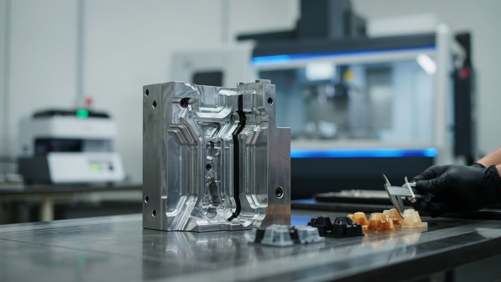
Comparing Fast Tooling and Production Tooling
| Factor | Rapid Tooling | Production Tooling |
| Main purpose | Validation, pilot runs, bridge production | Long-term, high-volume manufacturing |
| Typical lead time | A few days (printed) to 1 to 3 weeks (aluminium) | 6 to 12 weeks |
| Tool material | Printed resin, aluminium, soft steel | Hardened tool steel |
| Typical tool life | Tens to hundreds of shots (printed); about 1,000 to 10,000+ (aluminium) | 100,000 to 1,000,000+ shots |
| Upfront cost | Lower | Higher |
| Design changes | Easy to revise or replace | Slow and costly |
Production tooling still wins on cost per part at scale. Rapid tooling wins when speed, flexibility, and lower risk matter most.
How This Differs From Rapid Prototyping
The two terms are often confused. Rapid prototyping makes the part itself, usually by 3D printing or CNC machining, to check form and fit. Rapid tooling makes the mould, so parts come out of the actual moulding process in production-grade plastic. That makes the results of functional, thermal, and strength testing far closer to what the final product will deliver.
When Should You Choose This Approach?
Rapid tooling is a strong fit when:
- The design is likely to change after first testing
- You need functional parts in the final material, not just visual models
- You need a limited quantity for a launch, trial, or certification
- Investors or customers need to see production-like samples
- You want to reduce the risk of an expensive production mould
If the design is already proven and volumes are high from day one, going straight to production tooling may be more economical. For very small quantities, comparing vacuum casting and injection moulding for low-volume runs helps clarify where the cost crossover sits.
Limitations to Plan For
- Shorter tool life: Aluminium and printed tools wear faster under injection pressure, so they are not suitable for long production runs.
- Heat limits on printed inserts: Even heat-resistant resins struggle with high-temperature or glass-filled engineering plastics.
- Surface finish: Printed inserts may show layer lines and need polishing, and fine textures are harder to hold.
- Geometry trade-offs: Simplified actions can mean manual inserts and longer cycle times.
- Cost per part: Beyond a few thousand parts, a production tool usually becomes cheaper per part.
Design and Material Tips for Better Results
Design for moulding from the start. Designing plastic parts means accounting for functionality, structural integrity, and the moulding process itself. Keep wall thickness consistent and plan 1 to 3 degrees of draft on vertical walls. Avoid undercuts where possible, and keep parting lines simple. Loosen tolerances on non-critical features so the tool can be machined faster.
Test in the intended material where possible. Common injection moulding thermoplastics include PP, ABS, HDPE and LDPE, polycarbonate, nylon, acrylic (PMMA), PEI, PC/ABS blends, POM, styrene, PVC, and TPE/TPU for flexible parts. Validating with the same or a close material gives more reliable results. Parts made from thermosetting resins or composites are usually better suited to a different process, as explained in this comparison of compression moulding and injection moulding.
Match the method to your quantity. A handful of parts suits vacuum casting or printed inserts. Larger bridge runs usually suit machined aluminium tools.
Start with an accurate CAD model. If you are working from an existing physical part, 3D scanning and reverse engineering can create the digital model you need. This guide to reverse engineering for product design explains how a scanned part becomes a production-ready CAD file.
How Tesseract Supports the Journey From Prototype to Production
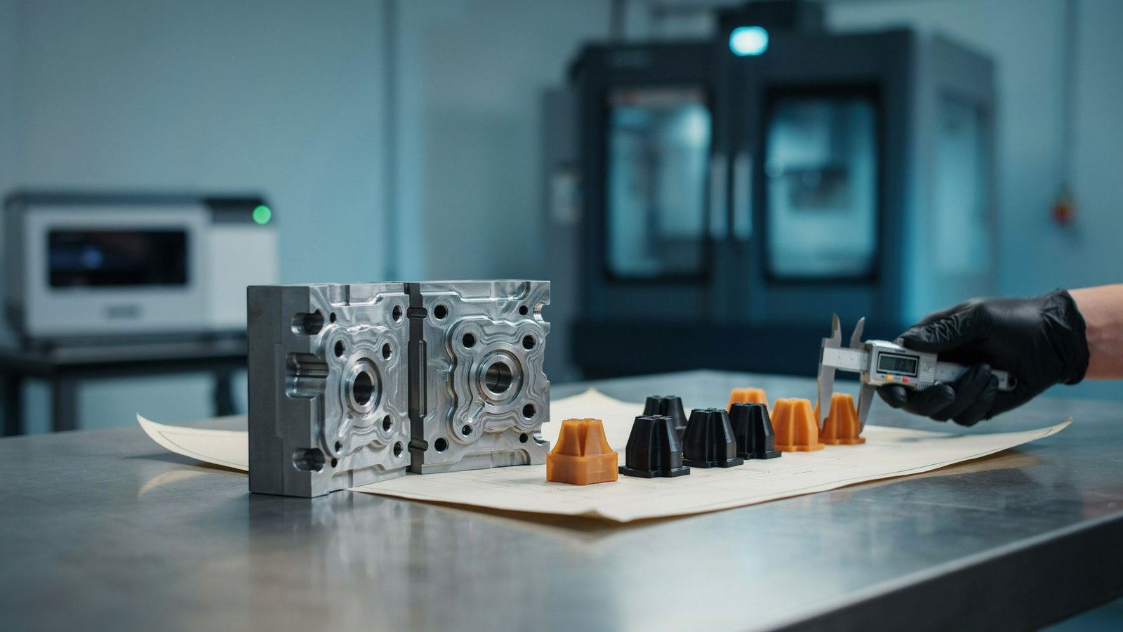
Tesseract brings over a decade of experience in 3D printing, design, and CNC machining. It operates from its Mumbai head office in Prabhadevi and a manufacturing facility in Boisar, with 5,000+ sq. ft. of space and 100+ machines across both sites. Its services cover every stage of the path described above: 3D scanning and reverse engineering, product design, 3D printing (FDM, SLA, SLS, DMLS, DLP, PolyJet and MJP), CNC machining, vacuum casting, and injection moulding.
Tesseract’s injection moulding service works with a broad range of thermoplastics. Its quality control includes first article inspection, statistical process control, and advanced metrology. Biocompatibility support covers USP Class VI and ISO 10993. Because prototyping, low-volume production, and full-scale moulding sit under one roof, projects can move from concept to small batch to mass production without switching vendors.
Ready to speed up your next moulding project? Upload your design to Tesseract for a quote.
Frequently Asked Questions
What is rapid tooling in injection moulding?
Rapid tooling is the quick, lower-cost manufacture of moulds or mould inserts used to produce prototype and short-run parts before investing in production tooling.
How long does rapid tooling take?
Printed mould inserts can produce parts within a few days, while machined aluminium tools typically take 1 to 3 weeks, compared with 6 to 12 weeks for hardened steel.
How many parts can a rapid tool produce?
Printed inserts typically handle tens to a few hundred shots, while aluminium tools usually last around 1,000 to 10,000 shots or more.
Is rapid tooling the same as rapid prototyping?
No. Rapid prototyping makes the part directly, whereas rapid tooling makes the mould that produces parts through the real moulding process.
What is the difference between direct and indirect rapid tooling?
Direct tooling prints or machines the mould straight from CAD, while indirect tooling first makes a master pattern and forms the mould from it.