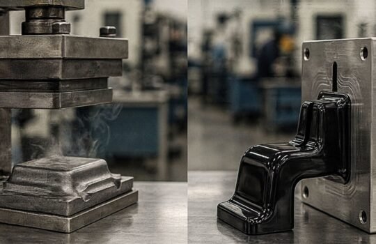
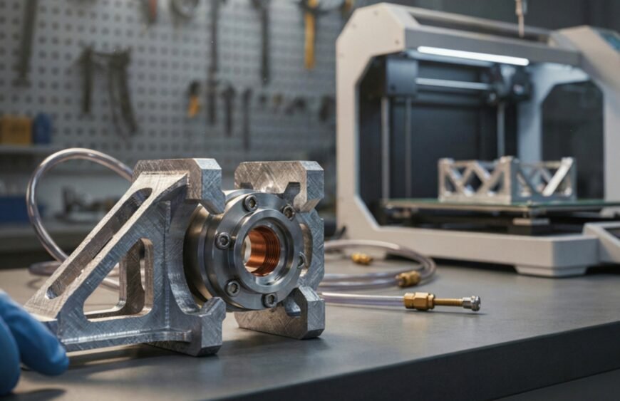
3D printing cuts the time needed to design, test, and deploy jigs and fixtures from weeks to days, letting manufacturers update assembly line tooling as often as their production needs change. For a shop floor team, that difference shows up directly in output: fewer stalled lines, faster changeovers, and tooling that fits the exact part in front of them instead of a compromise built for “close enough.”
Anyone who has run an assembly line knows that the tooling holding parts in place is just as important as the parts themselves. A jig or fixture that is even slightly off can throw off an entire batch. Yet for decades, these tools were treated as an afterthought, machined slowly and expensively, and rarely revisited once they were built. 3D printing is changing that relationship entirely.
What Jigs and Fixtures Actually Do
A jig guides a tool, such as a drill bit, to an exact location on a workpiece. A fixture holds a part securely in position while it is machined, welded, inspected, or assembled. Both exist for the same reason: to remove human error and variation from repetitive tasks, so that the hundredth unit off the line is identical to the first.
On a typical assembly line, this can mean dozens of small, purpose-built tools: alignment guides for wiring harnesses, drill templates for enclosures, gauge blocks for quality checks, and custom clamps that hold odd-shaped components steady. Each one is usually specific to a single product or even a single revision of that product.
Why Traditional Tooling Slows Manufacturers Down
Conventional jigs and fixtures are typically machined from aluminum or steel using CNC processes. That route works, but it comes with real costs. Machining a single fixture can take one to three weeks, depending on complexity and shop backlog, and a moderately complex tool often costs tens of thousands of rupees once you add design, material, and machine time.
The bigger problem shows up when a product changes. Every design revision, however minor, can mean an existing fixture no longer fits. Ordering a replacement means restarting the entire machining cycle, and until it arrives, the line either runs on a workaround or stops. For companies iterating quickly, especially in electronics, robotics, and automotive component assembly, this lag between design change and tooling readiness becomes a genuine bottleneck.
How 3D Printing Changes the Tooling Workflow
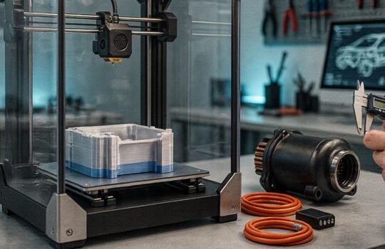
3D printing sidesteps most of that delay because a jig or fixture goes straight from CAD file to finished part with no tooling setup, no machine programming, and no material waste from subtractive cutting. A design tweak means editing the model and reprinting, often within a day.
This speed advantage compounds in a few specific ways:
Lower cost per iteration. Because there is no dedicated tooling or setup cost, printing a revised fixture costs a fraction of re-machining one. Teams can afford to prototype a jig, test it on the line, and refine it two or three times before settling on a final version, something that was rarely practical with machined tooling.
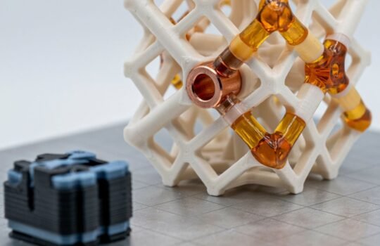
Design freedom. Additive manufacturing builds a part layer by layer, so internal channels, organic contours that match a part’s exact geometry, and lightweight lattice structures are all possible without adding cost. A fixture can be shaped to cradle an oddly contoured housing or route cables through it, options a CNC mill cannot easily produce.
On-demand replacement. If a jig cracks or wears out mid-shift, a replacement can be printed and back on the line the same day rather than waiting on a machinist’s queue.
Low-volume economics. Most jigs and fixtures are needed in quantities of one to a handful per line. 3D printing has no minimum order quantity and no amortized tooling cost to justify, which makes it naturally suited to this kind of low-volume, high-mix production support.
Choosing the Right Process and Material
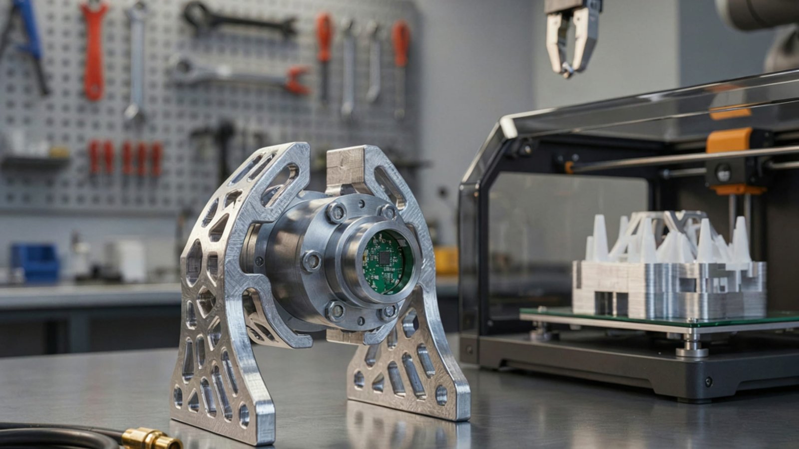
Not every fixture needs the same technology. FDM printing in engineering-grade materials such as ABS, ASA, or carbon-fiber-reinforced filament is generally the first choice for structural jigs, drill guides, and clamps that need to withstand repeated handling and moderate mechanical load.
SLS is a strong option when a fixture needs finer tolerances or has thin, intricate features, since the process does not require support structures inside the part. For fixtures that also need to check dimensional accuracy, SLA can deliver the surface finish and precision required for gauges and inspection tools.
Material selection matters as much as the process. A fixture sitting near a heat source on a line needs a higher-temperature-resistant polymer, while one that only needs to hold a lightweight plastic housing in place can use a simpler and cheaper filament. Getting this match right is usually a five-minute design-for-manufacturing conversation rather than a major redesign, which is part of why iteration is so much faster with printed tooling.
Where This Shows Up on Real Lines
Electronics assemblers use 3D-printed jigs to align PCBs and wiring harnesses precisely enough for automated soldering and testing stations.
Automotive component makers print fixtures to hold brackets and housings steady during drilling or welding, updating the fixture each time a supplier changes a part’s dimensions.
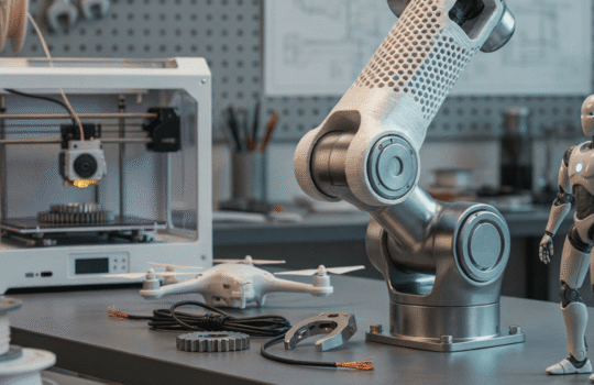
Robotics manufacturers, where product designs evolve quickly through multiple prototype generations, rely on printed jigs to keep pace with iteration cycles that would otherwise be constrained by tooling lead time.
When Machined Tooling Still Makes Sense
3D printing is not a universal replacement for machined tooling. Fixtures that face continuous heavy mechanical load, high-volume production runs over multiple years, or extreme temperatures are often still better served by metal tooling.
The right approach for most manufacturers is a hybrid one: use 3D printing for prototyping tooling concepts, low-to-medium load fixtures, and any tool likely to need revision, and reserve machined metal tooling for the handful of fixtures that need to survive years of continuous heavy use unchanged.
Getting Started
Manufacturers looking to reduce tooling lead times typically start with a single problem area, such as a fixture that gets revised often or one that is currently a bottleneck, and print a working version to validate on the line before rolling the approach out further.
Tesseract works with manufacturing and robotics teams across India to design and print jigs, fixtures, and assembly aids in FDM, SLS, and SLA, matching material and process to each tool’s actual working conditions rather than defaulting to one process for everything.
Frequently Asked Questions
Can 3D printed jigs and fixtures handle daily use on a production line?
Yes, when you match the material and process to the load. Engineering filaments like ASA and carbon-fiber reinforced nylon hold up well under repeated daily handling and moderate mechanical stress.
How much faster is 3D printing compared to machining a fixture?
A printed fixture typically moves from design to finished part in one to three days, compared to one to three weeks for a machined equivalent, since there is no tooling setup or machine programming involved.
Is 3D printing cost-effective for a single fixture?
Yes. Because there is no minimum order quantity or dedicated tooling cost, printing a single fixture is usually far cheaper than machining one, especially when a design is still likely to change.
What 3D printing process is best for assembly line jigs?
FDM in engineering-grade materials is a common starting point for structural jigs and clamps, while SLS suits fixtures with fine or intricate features, and SLA suits gauges that need high dimensional accuracy.