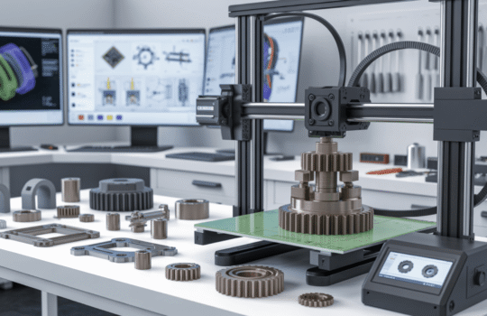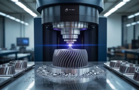
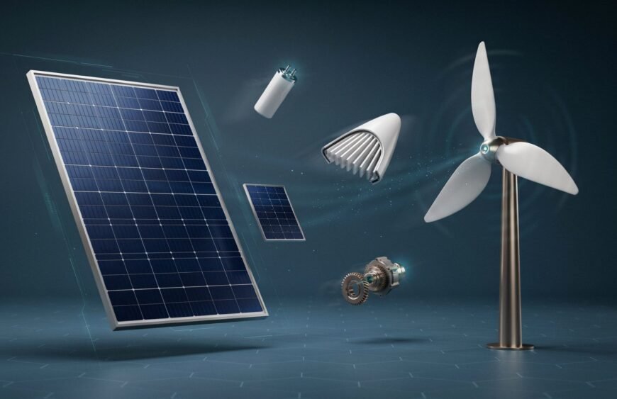
3D printing helps renewable energy manufacturers cut prototyping time for solar and wind components from weeks to days, letting engineers test brackets, housings, connectors, and turbine parts through several design iterations before committing to expensive tooling or metal fabrication.
The renewable energy sector runs on constant iteration. Solar panel mounts need to survive decades of thermal cycling. Wind turbine components face wind loads, vibration, and weather extremes that vary by site. Getting a design right the first time is rare, and traditional prototyping methods (CNC-only runs, injection mould tooling, sheet metal fabrication for every version) make each iteration slow and costly. Additive manufacturing changes that equation by letting engineers print, test, adjust, and reprint a part in the same week.
Why Renewable Energy Engineering Teams Use 3D Printing for Prototyping
Solar and wind hardware is developed by small, fast-moving engineering teams that need physical parts to validate fit, airflow, load paths, and assembly before locking in a final design. Rather than waiting on a CNC job queue or a sheet metal vendor for every revision, teams can 3D print a working prototype, test it on a bench or in a wind tunnel, and print a revised version the same day. This shortens the design validation loop for connector housings, junction boxes, mounting brackets, and small turbine components considerably.
Cost is the other driver. A single aluminium mould for an injection-moulded bracket can run into lakhs of rupees and take weeks to machine. If the bracket geometry changes after testing, that tooling cost is sunk. Printing the same bracket in engineering-grade nylon or ABS lets a team validate the geometry first, then move to metal casting, sheet metal, or injection moulding only once the design is confirmed.
Solar Component Prototyping Applications
Solar hardware prototyping typically falls into a few recurring categories:
Mounting brackets and rail clamps. Solar racking systems use brackets that must resist UV exposure, thermal expansion, and wind uplift. Printing these in glass-filled nylon (PA66-GF30) or carbon-fibre-reinforced ABS lets engineers test clamping force and thread engagement before cutting steel or aluminium tooling.
Junction box and connector housings. MC4 connectors, combiner box enclosures, and cable gland housings need tight tolerances for weatherproofing. SLA and DLP printing produce the fine detail needed to test O-ring seats and snap-fit closures before the design moves to injection moulding.
Tracker system components. Single-axis and dual-axis solar trackers use gears, bearing housings, and actuator mounts that benefit from functional prototyping in nylon or PC before final parts are CNC machined or die cast.
Inverter and BOS enclosure mockups. Balance-of-system components, including inverter housings and disconnect boxes, are often printed first as fit-check models to confirm cable routing and ventilation before sheet metal fabrication begins.
Wind Component Prototyping Applications
Wind energy hardware spans a wider range of scale, from small rooftop turbines to utility-scale blade components, and 3D printing supports different stages of that range:
Scaled blade and nacelle models. Aerodynamic testing on scaled turbine blades is a common early-stage validation step. FDM and SLS printing produce lightweight, dimensionally accurate scale models that can be tested in wind tunnels before full-size tooling is committed.
Sensor housings and control enclosures. Anemometers, pitch control sensors, and SCADA enclosures need custom housings that fit specific mounting points. These are strong candidates for FDM or SLS prototyping in ASA or PA6, both of which hold up to outdoor exposure better than standard PLA or ABS.
Gearbox and drivetrain fixtures. Functional prototypes of small gearbox housings, bearing retainers, and coupling components can be printed in glass- or carbon-filled engineering plastics to validate fit and clearance before metal casting or CNC machining of the production part.
Jigs and fixtures for assembly and testing. Beyond the turbine parts themselves, 3D printing is widely used to produce custom jigs, alignment fixtures, and test rigs used during turbine assembly and inspection, which rarely justify traditional tooling given their low volume.
Materials That Matter for Renewable Energy Prototypes
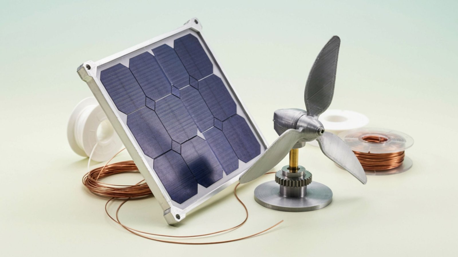
Material choice depends on what the prototype needs to prove. For a straightforward fit-check or form study, standard ABS or PETG is usually enough. For prototypes that also need to survive some mechanical or environmental testing, glass- or carbon-filled engineering plastics such as PA66-GF30, PA6-CF20, or ASA hold dimensional stability better under heat and outdoor exposure. Where a prototype needs to closely mimic the strength or thermal behaviour of a final metal part, DMLS printing in materials like Aluminium AlSi10Mg, Stainless Steel 316L, or Titanium Ti64 lets engineers validate load-bearing brackets and structural mounts in a metal that behaves close to the production alloy. CNC machining in aluminium, stainless steel, or high-strength steel remains the right call when a prototype needs to be tested to near-production tolerances.
Choosing the Right Process
FDM works well for early-stage brackets, housings, and fixtures where speed and cost matter more than surface finish. SLA and DLP suit small, detailed components like connector housings and sensor enclosures that need tight tolerances and clean surfaces. SLS is a strong fit for functional nylon parts that need to handle some mechanical stress without support structures limiting geometry. DMLS is reserved for structural metal prototypes where the part needs to behave like the final production component under load. For parts headed toward mass production, CNC machining, sheet metal fabrication, or injection moulding validate the geometry in the actual production material and process.
From Prototype to Production
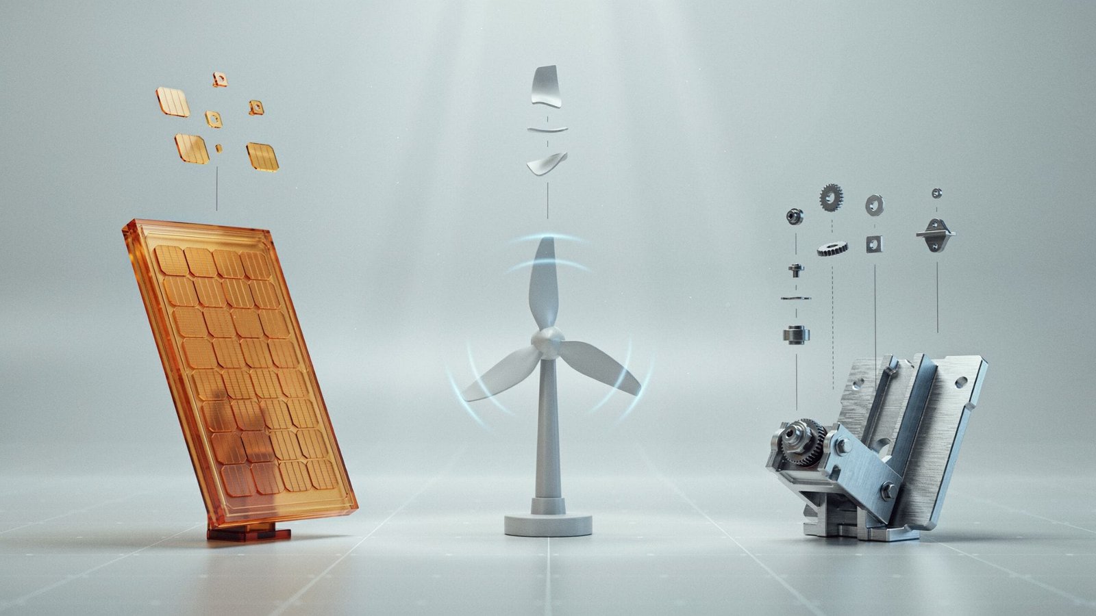
A typical renewable energy prototyping workflow moves from a rough CAD concept to a 3D-printed functional prototype, through one or two rounds of design revision based on bench or field testing, and finally into the production process, whether that’s CNC machining, sheet metal fabrication, metal casting, or injection moulding, depending on volume and material requirements. Keeping this progression in mind during the design phase avoids rework later, since a part designed only for FDM printing may need geometry changes before it can be tooled for mass production.
Working With a Manufacturing Partner
Solar and wind hardware development moves faster when design, prototyping, and manufacturing sit with one partner rather than being split across multiple vendors. Tesseract 3D runs FDM, SLA, SLS, DMLS, DLP, and PolyJet 3D printing alongside CNC machining, sheet metal fabrication, metal casting, and injection moulding from its Mumbai (Prabhadevi) and Boisar facilities, with most prototyping projects completed in 2 to 7 days. That range of processes under one roof means a bracket, housing, or scaled component can move from a printed prototype to a metal or injection-moulded production part without changing vendors mid-project.
Frequently Asked Questions
Can 3D printing produce parts strong enough for outdoor solar and wind installations?
Functional prototypes in materials like ASA, PA66-GF30, or DMLS-printed metals can withstand meaningful mechanical and environmental testing, though final production parts for long-term outdoor deployment are typically validated in CNC-machined or cast metal.
Which 3D printing process is best for solar bracket prototypes?
FDM in glass-filled nylon or carbon-fibre ABS is a common starting point for solar bracket prototypes, since it balances speed, cost, and enough mechanical strength for fit and load testing.
How long does it take to prototype a wind turbine sensor housing?
Most functional prototypes for enclosures and housings are completed within 2 to 7 days, depending on part complexity and the printing technology used.
Is metal 3D printing used for wind or solar components?
Yes, DMLS printing in materials like Aluminium AlSi10Mg or Stainless Steel 316L is used to prototype structural brackets and mounts where the part needs to behave close to the final metal component.